Hydrostatic Transmission
They are intended for driving in agricultural machines (forage harvesters, combine harvesters, self-propelled threshers produced by “Gomselmash”, “Bryanskselmash”, “Rostselmash”, “Agromashholding”), in road-building machinery (asphalt compactors, concrete mixers “Tigarbo”, “TZA”).
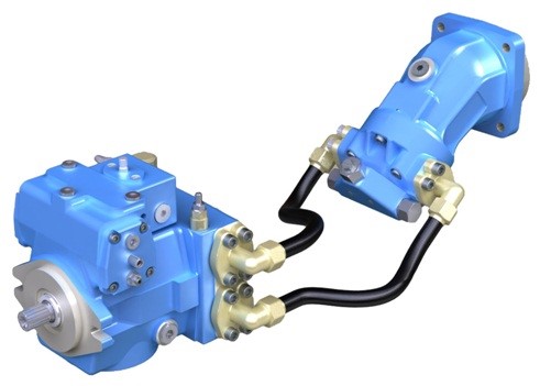
Hydrostatic transmission – closed hydraulic system consisting of hydraulic pump and hydraulic motor.
Hydrostatic transmission is designed to transmit mechanical energy from the drive motor to the executive body of the product.
The main ports of the pump are connected by hydraulic lines to the main ports of the hydraulic motor. The working fluid flows in any direction from the pump to the hydraulic motor and then returns to the pump in this closed circuit.
Each of the hydraulic lines can be under high pressure.
In the operating mode, the position of the inclined washer determines which line is under high pressure as well as the direction of the working fluid flow.
Pump and motor need drain lines to remove hot liquid from drain cavities.
The motor must be connected to the drain line through a drain hole located at the top point to ensure that the drain cavity of the motor is filled.
It is recommended to connect the drainage line of the hydraulic motor to the lower drain hole of the pump, the drain of the combined leaks to the hydraulic tank is carried out through the upper drain hole of the pump. Heat exchanger is designed to cool the working fluid, which is a part of the drainage leaks, before it gets into the hydraulic tank.
It is successfully used on such machines:
– combine harvester “Essil – 760.1”
– Grain harvester “Polesie – GS-1218”
– Forage harvester KSC-600
– Self-propelled thresher KZK 12-010 0000B-21
416 series pumps and their main components.
Hydraulic pumps adjustable axial piston with inclined washer 416 series are designed for operation in closed hydraulic circuits. Hydraulic pump feed is proportional to shaft speed and operating volume. The working volume is infinitely adjustable from zero to the maximum value in each direction. The direction of fluid supply can be reversed by tilting the washer in the opposite direction to the neutral position. The pumps are made in cast iron housings. In the oscillating unit of the hydraulic pump a spherical distributor and a steel bronze cylinder block are used, which allowed to increase the maximum working pressure and increase the life time. The working volume of the hydraulic pump is regulated by changing the angle of inclination of the washer. Hydraulic pumps can limit the maximum working volume in each direction with adjusting screws.
All connection dimensions are made according to ISO/SAE standards.
Control mechanisms.
1. Mechanical proportional servo control. The servo control mechanism is designed to convert the primary mechanical signal into a reinforced servohydraulic signal, by means of a servo regulator deflecting the tilting washer (by an angle of ± 20º) with a linear change of the working volume of the product corresponding to a certain position of the control lever. The proportionality of the angle of deflection of the tilt washer to the angle of deflection of the control lever is ensured by the mechanical feedback between the servo piston and the servo control mechanism.
2. Hydraulic proportional control. The hydraulic control mechanism is designed to convert the input hydraulic control signal into a reinforced servohydraulic signal, by means of a servo regulator deflecting the tilting washer. The spool of the control mechanism directly controls the servo piston and is connected to it by mechanical feedback. The feedback ensures that the tilt washer deflection is proportional to the change in the value of the hydraulic control signal (control pressure).
3. Proportional electric control. The mechanism of proportional electric control is structurally similar to the mechanism of proportional hydraulic control. However, instead of the hydraulic control signal, an electric 12V or 24V is used. The electrical PWM control signal acts on two proportional electromagnets, which convert it into a mechanical force of the control spool movement. In this way, the electrical control mechanism converts the electrical PWM control signal into a hydraulic control signal for the servo piston and therefore the tilting washer. The spool of the electric control mechanism is connected to the servo-piston mechanical feedback. The feedback ensures that the inclined washer deviates in proportion to the change in the control signal of the electrical PWM control signal.
- position discrete electric control. The control mechanism is an electrically controlled spool hydraulic valve. When a 12V or 24V signal is applied to one of the electromagnets, the spool moves from the starting position to the extreme position, thus directing the servo control pressure to the corresponding cavity of the servo piston. The servo piston deflects the inclined washer of the pump to the maximum angle in the corresponding direction. When the control signal is removed from the electromagnet, the spool returns to its original neutral position.
5. Hydraulic proportional control without feedback. The control hydraulic signal acts directly on the servo piston that deflects the tilt washer. The angle of deflection of the tilt washer is proportional to the value of the control hydraulic signal only at constant pressure in the power line (at constant load). When the hydraulic drive load changes, the control graph also changes, the proportionality remains.
6. Proportional electric control without feedback. The control mechanism is structurally based on two electrically controlled proportional pressure-reducing valves. Each valve is mounted in the servo piston control line. When a 12V or 24V signal is given, the valve proportional regulates the servo control pressure acting on the servo piston. The angle of deviation of the tilt washer is proportional to the value of the electrical PWM control signal only at constant pressure in the power line (at constant load). When the hydraulic drive load changes, the control graph also changes, the proportionality remains.
406 Series hydromotors and their main components.
Unadjustable axial piston motors with inclined washer.
Hydromotors convert the energy of the working fluid into the mechanical energy of the shaft rotation. The direction of rotation of the hydraulic motor shaft is determined by the direction of the working fluid supply. The speed of the shaft rotation is determined by the amount of liquid supplied. The torque on the motor shaft is determined by the pressure of the hydraulic fluid. Hydromotors are made in cast-iron housings. In the oscillating assembly of the hydraulic motor a spherical distributor and a steel bronze block of cylinders are used, which allowed to increase the maximum working pressure and increase the resource. The flushing (rinsing) unit is built into the back cover of the hydraulic motor.
All connection dimensions are made according to ISO/SAE standards.

